
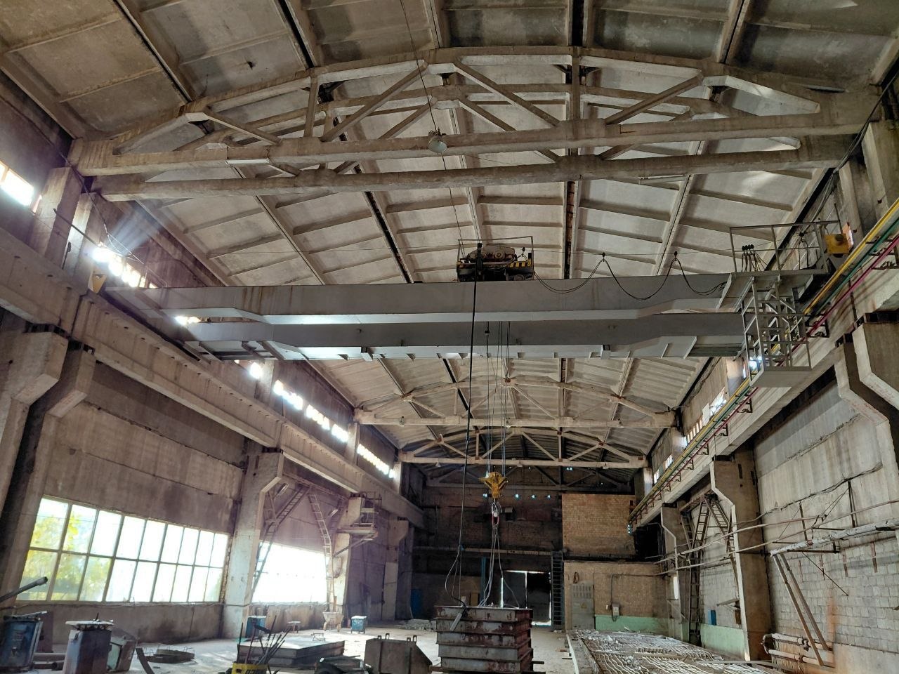
The material below is a shortened version of a technical report.
To maintain confidentiality, photographs, client address, part of the equipment identification data, references to standards, and report attachments included in the full version have been removed.
Report
on identified technical condition findings of an overhead crane
Shortened version
Client:
Equipment:
Overhead crane
Site:
Prepared by:
Volodymyr Aleksieiev
Private Entrepreneur
Inspection date:
January 8, 2026
This report was prepared by Private Entrepreneur Volodymyr Aleksieiev following the client’s request to document the actual technical condition of the crane and to prepare a list of engineering measures required for restoration of operational condition and further modernization.
No technical documentation for the crane was provided at the time of inspection, including:
— crane passport;
— instrumental inspection reports;
— partial or full technical inspection records.
The only available source of identification data was the information plate installed on the crane cabin, which contained the following information:
— Equipment type: overhead crane;
— Rated lifting capacity: 10 t;
— Date of instrumental inspection: 16.06.2004;
— Date of partial technical inspection: 19.02.2020;
— Date of full technical inspection: 19.02.2020.
No additional identification or passport data, including manufacturer, serial number, or year of manufacture, were available at the time of inspection.
The manufacturer and year of manufacture were not officially identified.
Approximate crane age was evaluated based on structural and electromechanical features, including motor types, control equipment, power supply arrangement, and mechanism layout. Based on these characteristics, the crane belongs to a generation of overhead cranes manufactured approximately between 1965 and 1985, with the most probable manufacturing period being 1982–1985.
This assessment is informational only and does not represent official identification of the crane. All conclusions in this report are based exclusively on actual inspection, measurements, and analysis of the crane condition at the time of inspection.
Technical Findings
1. Steel Structure and Geometry
No positive camber of the main girders was detected.
Negative deflection of the main girders (downward) of approximately 6 mm was detected in the area located approximately at 1/3–1/4 of the span on the trolley side.
No macrocracks were detected in the girder steel. The condition of possible microcracks was not evaluated without non-destructive testing.
No horizontal deformation of the upper girder flanges was detected.
Local buckling of side plates was detected within acceptable limits.
No separation of side plates from diaphragms was detected.
Significant contamination by oil, dust, and foreign materials was detected, creating increased fire hazard conditions.
2. Trolley Runway and Rails
Alignment of trolley runway rails is disturbed in the horizontal plane and requires restoration in both horizontal and vertical alignment.
Oil-contaminated dust deposits are present on trolley rails.
Rail contamination causes bridge vibration during trolley travel.
Trolley rails require cleaning.
Crane runway rails require cleaning.
3. Travel Wheels and Drives
Travel wheel type: wheel diameter 400 mm, wheel width 150 mm, flat-head rail width 80 mm.
The hydraulic thruster of the trolley travel drive is physically disconnected and wiring terminals are left open.
On the trolley line side of the bridge travel drive, the hydraulic thruster is connected but defective; the rod moves freely without resistance.
Bridge brakes on the trolley line side are released and effectively non-operational.
At movement start in either direction, the trolley line side of the bridge lags approximately 150 mm behind the opposite side.
Restoration of the external wheel flange on the drive wheel on the cabin side is required.
Inspection of wheel axle box bearings exposed to electric current is required.
Inspection of trolley wheel axle box bearings is required.
Inspection of all crane gearboxes is required.
4. Electrical System and Controls
Low-voltage control circuits are absent; crane controls operate without a step-down transformer.
Three-phase 380 V power is supplied through open conductor lines.
220 V circuits are supplied through a neutral formed via the IRAK-250 cabinet housing.
The IRAK-250 housing is grounded to the crane bridge structure.
Due to this arrangement, neutral current passes through travel wheel bearings into the crane runway.
After current collector shoes, cables are routed directly into the cabin to disconnect switches inside the IRAK-250 cabinet.
Electrical wiring is outdated, including sections with fabric insulation.
Wiring is laid directly on steel structures.
Master controllers operate unstably.
Incorrect hoisting mechanism operation was detected: after returning the controller to zero position, lowering continues; stopping occurs only by reverse current application.
Lowering defects occur intermittently: repeated failures are followed by temporary recovery and repeated malfunction.
Nearly all cable glands and flexible metal conduits have visible damage.
Flexible metal conduits are not grounded.
Conductor lines require cleaning.
The current condition of electrical equipment, insulation, cable routing, and switching equipment does not allow compliance with required fire safety and electrical safety standards without complete replacement.
5. Operating Conditions
The workshop was previously used for reinforced concrete production.
Future operation is planned for fabrication of steel structures from carbon steel.
Submerged arc welding and shielded gas welding (CO₂ and argon) are planned.
Conductive industrial ventilation systems will be present inside the building.
Electrical equipment and control cabinets require protection class not lower than IP54.
Braking resistors must be designed with external radiators.
6. Access and Maintenance
Permanent crane access systems are available and generally satisfactory.
Removal of the operator cabin would require revision of crane access arrangements and is considered undesirable.
Related Engineering Case
Based on the technical diagnostics results, a separate set of engineering measures was developed to restore the crane to a safe, controllable, and predictable technical condition with the possibility of further return to operation.
Engineering Measures for Restoration of a 10 t Overhead Crane